
I'm going to try to explain a kind of fast-and-loose McGyver-like understanding of electricity, the kind that used to exist in 1940's books that explained how to build your own radio and assumed you had a box of random parts lying around (but without that assumption). They also assumed that you didn't need to get precious and precise about it, that you could just muck about by mostly feel till you got something that worked. Optimization and efficiency was for proper electrical engineers. I think this is a good approach for many—if you start here and get over an initial sense of intimidation, you can later get into fine tuning if you want to. (If you are in fact an electrical engineer, reading this may make you want to tear your hair out. Sorry!) We are surrounded by electronics, but to many of us, it's alien magic. This approach is intended to make it more familiar and comfortable, like making stuff with scissors and tape.
Hands on
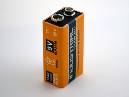
First, let's touch some electricity. It's hard to understand what you can't see or touch. Get a 9 volt battery from your local grocery store or kiosk. It's the one shaped like a block instead of a cylinder, with the two metal lego-like connectors at the top of it.
Take it out of its packaging and put your tongue on one of the connectors. Should taste like nothing or like metal. Now, (Note: this will hurt a tiny bit) briefly put your tongue on both connectors at the same time. Ow! What just happened?
An analogy
Notice the battery has two types of connectors, + and -. Every battery of every size and type has these two. It says which is which right on the battery. The shape of the connector doesn't matter. Connectors are just metal contacts, and the different shapes are just to make it convenient to attach the battery to different things.
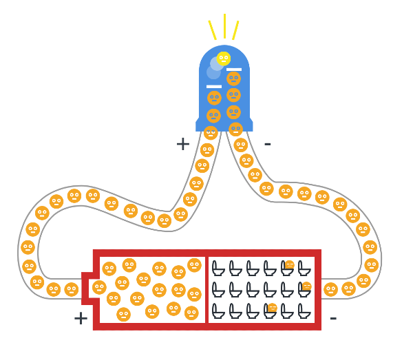
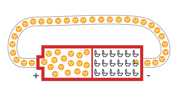
Imagine that inside the battery there are two rooms. In one room (the MINUS room) there are a bunch of toilets:

In the PLUS room are a bunch of kids that really need to pee.
These kids are highly motivated to run towards the toilets as soon as a corridor opens which can take them there. Otherwise, they sit in the room and suffer and wait. (Lots of potential energy there. 9 volts of it, in fact.)
A moment ago, your tongue was that corridor. Those little kids ran out of their room, through the saliva on your tongue, and into the toilet room with great relief. This leaves a sour taste. (some cool details on how you can get different tastes with different levels of current here)
But other things could be that corridor. Anything made of metal, really, like aluminum foil, or a nail, or a pencil lead (to some extent) or water (ideally with some salt/minerals in it), or a banana, or even your body if they need to pee badly enough. The kids in that 9V battery don't need to pee that badly. The ones in the plug in your wall though, need to pee BADLY. Like 120V to 220V worth, (depending on where you live) which is a lot of motivation to push through the resistance of the cells in your body, thereby frying you from the inside as they aim for relief in the ground, which is the ultimate room of toilets. (They'd prefer to run through something metal, but you'll do in a pinch) So don't play with those bigger-Volt kids till you really know what you're doing.
Meanwhile the kids in the 9V battery are pretty chill. The kids in the batteries you're probably most familiar with (the cylindrical AA and AAA ones) are even more chill at 1.5V each. The most common coin cells (the ones that look like coins) are often 3V. This is not going to hurt you.
The only thing that can really go wrong is something called a short circuit. This is when you have a corridor straight from PLUS to MINUS with nothing useful in between to slow the kids down—no LED, no motor, no resistor, nothing. The kids just sprint.
⚠️ Two bad things can happen:
- The wire heats up. If the corridor is thin (like a wire, or steel wool), the friction of all those kids shoving through at once generates heat. Thin wire = more friction = more heat. This can burn you or start a fire.
- The battery heats up. Even if your wire is thick enough to stay cool, the battery itself is working way too hard. It’s like forcing all those kids through the door at once—the door (the battery) takes the strain. The battery can get hot, leak chemicals, swell up, or in extreme cases with bigger batteries, vent hot gas.
For an example of wire heating up, get some steel wool and touch a 9V battery to it. Or just watch someone else do it:
Steel wool burning when connected to a 9V battery
The steel wool burns because it’s so thin. Thicker wires won’t catch fire as fast, but that doesn’t mean a short circuit is safe—it just means the heat shows up somewhere else (usually the battery).
You probably didn't want to waste the energy of the kids on just heating up the wire anyway, right? Let's see what we can do with it.
Do something useful
If you put something in the way of the kids that they must run through before reaching the toilets, you can use their energy, as long as they know they WILL eventually reach the toilets. They're all in a long line in the corridor, and if at any point one of them has to stop, they all stop. If they can all move forward, they all move.
You want to make a connection from the ➕PLUS to a 💡THING to the ➖MINUS in a nice unbroken loop. Some examples of THINGS:
- a motor
- a buzzer
- an LED (a light)
Each of these has two metal contact points, one to let the kids in, and another to let the kids out.
You can either buy these parts from an electronics hobbyist shop online (links at the end of this post) or take an old toy apart that has lights and movement and/or makes an annoying eeee sound--they're all in there, and they usually still work just fine even if the toy itself doesn't anymore. (More on this at the end of the post)
The LED

LED stands for Light Emitting Diode. Diode means it's a weird bit of corridor with a one-way revolving door. Try to make the kids go in the wrong way and they won't be able to. (plain diodes that doesn't emit any light also exist, but more on those later perhaps) LEDs have a long(+) leg and a short(-) leg, and to make it work you need to attach the long leg to the ➕PLUS room to let the kids in through there.
The easiest way to see this is to put an LED around a 3V coin cell, like so:

Play around with this. Flip the LED around, make the leg touch and not touch one of the contacts and see what happens. If you don't have the long leg on the PLUS side, it won't work. If both legs don't touch their respective contacts, it won't work (kids can't get to toilets). If one of the legs touches the plus and minus sides at the same time, it'll get warm/hot.
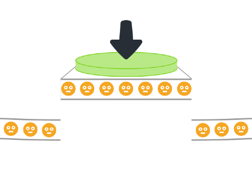
Once the kids get in, there's a step for them to jump up to. Each one that jumps up releases a tiny burst of light.

However, if the kids don't need to pee badly enough, they won't have the motivation to jump up, and the LED won't emit light. Likewise, if there are too many of them at once jumping too hard, they can break the step and burn out the LED.
Controlling the corridor
When you open and close the loop to the battery, you can see the LED turns on and off. What else does this?
A button.
There's nothing magic about a button. It's just something that makes two bits of metal touch or not touch. It's entirely mechanical. When you push down, you're pushing down a kind of metal "bridge" that connects two separate metal bits. Then the kids can run across it. Let go, and the metal pieces are separate again.
A button has two bits of metal sticking out of it, one for the kids to run into, and one for the kids to run back out of when the "bridge" is down for them to get across.
This means you can make your own button out of literally any mechanism that makes two metal pieces touch. One clever one is to have a metal marble roll down a wooden groove to a spot which has two pieces of copper tape on either side of the groove at the end.
A switch.
This does the same as a button on the inside; it's just a different mechanic on the outside. Some switches have more than one metal connector so you can turn one thing off while turning another on, or turn both off.
A resistor.
What if we want an LED to shine a bit dimmer than full-on?
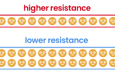
Resistors make the corridor the kids are running through more narrow, so they are allowed to go through, say, only two at a time instead of ten abreast. Making the corridor narrow is adding resistance.
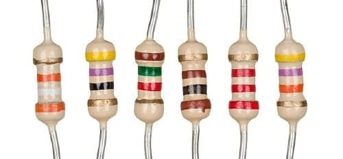
Resistors come in various levels of resistance, which are indicated by their colored bars, each of which represents a number so you can tell one resistor's resistance from another's. Google "resistor color codes" to find out more about these, (there's even a game around learning them) but for our purposes you probably only need three or four different "strengths" which you can then attach in-line one after another to increase their effects. This is where you can experiment. Put different resistors in an LED circuit and see how it affects the brightness of the light, and that should give you a sense of how strong each one is.
Don't worry about breaking stuff. These components are cheap, and if you're doing this with a 3V coin cell nothing's going to break in any case.
The number of kids going through the corridor per second is the current. You can now imagine that if they're not very motivated to pee (low voltage) they won't be pushing quite so hard, so they won't go through very fast, and that means low current. But if you have low voltage and a nice wide corridor with low resistance, you'll increase the current. You may have seen this before:
I = V/R, or Current = Voltage divided by Resistance
That "I" above is confusing (why isn't it C for Current?), and you can blame the French for that. It stands for intensité de courant, or Intensity of current. Thanks a lot, French people.
You can also think of it like this:
How many kids are going through the corridor each second = motivation to reach the toilets / corridor width
I guess you could also think of it as measuring how intense the throng of desperate kids is at a certain part of the circuit. How many of them are passing through there, considering how much space they have, and how hard are the kids pushing each other forward?
Having said all that, you won't need this to just mess around a bit, but if things start going wrong and something isn't working you can find out why by keeping the above in mind. Each component you add to a circuit (a collection of parts attached with wires to a power source like a battery) has a range of how many kids it wants running through it at once. Too little and it won't work. Too much and it will break.
The tool to measure voltage, resistance and current is called a multimeter, but again, you don't need to worry about it right now if that feels overwhelming at the moment. The most useful beginner tool it provides is called a continuity tester, which is usually represented by an icon that looks like some kind of sound or alarm. You can use this to check that everything is connected properly. Touch the one contact to a spot in the circuit, and the other to a spot beyond where you think the connection might be broken. If it buzzes, electricity is getting through. If it's silent, it isn't. You can test the continuity tester is working just by touching the two multimeter connectors to each other.

So let's get back to your LED and battery set-up. If you put a resistor between the battery and the LED, the LED will be a bit less bright because fewer kids are running through it per second.
Keeping things together
At this point you may have found that holding things together with your fingers is a pain. You can use a breadboard to keep things connected, or soldering (melting a blob of metal with a low melting point over two wires to connect them) but what I recommend at first is either just twisting the legs of components together if the legs are long enough, or using copper tape, or both. You can see copper tape being used in the pictures below. What you want is strong contact between the two metal bits.
Click through to see these components and a potentiometer in action
Some components have very short legs and are a bit of a pain without a breadboard, but you can also find small alligator clips to attach to those. The main thing is to make sure metal touches metal in some significant fashion. Copper tape is nice for this because it's easy like tape and it adds metal to the connection, which means more material for the "kids" to run through.
Getting fancy
By now you probably have it in your head that to make electricity do something it needs to go in a loop from one end of the power source to the other, and then you'll want to put things in the way of the running kids. One type of thing is an output (an LED, a buzzer, a motor, something that does something), and another type of thing is something that controls the kids themselves (a button, a resistor, a switch).
Here's a formula that works:
[➕] ———[control]———[output]———[➖]
[➕]———[switch]———[LED]———[➖]
[➕]———[resistor]———[motor]———[➖]
[➕]———[switch]—[resistor]———[motor]———[➖]
Now all you need to make a bunch of different things is to know what parts are out there, and maybe some of their quirks.
Potentiometer (dimming)
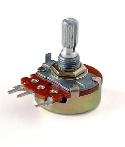
Sometimes you want to control how things fade, like the brightness of a light or the volume or pitch of a sound. Potentiometers are the knobs or sliders that you often find on audio equipment or dimmers on walls. What they do is split the corridor between two exits. (It's called a "voltage divider" for this reason.) This is also why they have three legs instead of two. The two corridors share the middle leg and turning the knob lets more kids out one leg and less out the other.
Knob all the way left: 100% left leg, 0% right
Knob a bit left: 75% left leg, 25% right
Knob middle: 50% left leg, 50% right
If you attach an LED to each leg and turn the knob right and left, one LED will dim as the other gets brighter and vice versa.
LEDs attached to a battery and a potentiometer. All [-] wires are attached to the [-] on the battery, and the outer legs are attached to the the LEDs, which are attached to the [+]. Turning divides the battery power between the left and right LED.
If you just use two of the legs (middle and one of the side ones) and ignore the third, you simply control that one corridor, and let zero-to-all kids through it.
Now it might also be clear why "turning the volume up to eleven" just means "let all the kids run free".
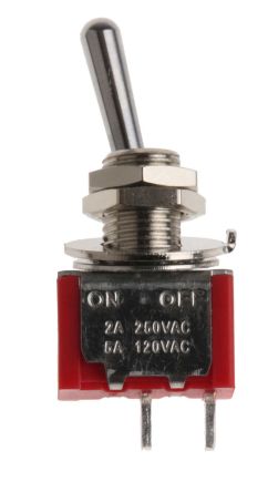
Tilt switch (falling over)
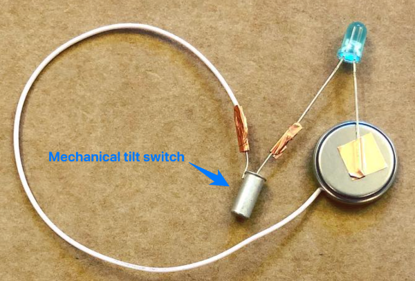
Buttons are useful, but the tilt switch connects two metal contacts by having a metal ball inside a cylinder roll over and touch both of them. In other words, it's a button that activates when you tilt it. For example, with this you could make an alarm which buzzes if something is knocked over.
Reed switch (magnets)
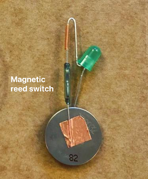
Reed switches are made of glass tubes, so if you look into one with a magnifying glass you should be able to see two flat metal wires almost touching inside. If you bring a magnet near, they stick together, and the kids can run across. If you put a magnet at the end of a chopstick, and hide a reed switch -controlled circuit in a toy, you can make the toy respond to a "magic" wand.
More things that do things
Motor (movement)
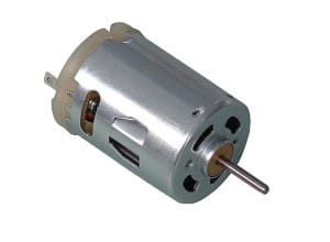
Motors are easy to use: they have two legs, and you can make the motor turn in one direction by having the kids run in one way and out the other, or flip PLUS and MINUS and have the direction of the motor flip accordingly. You can imagine it as a treadmill that the kids keep going as they run across it.
Motors have another use though: If you don't have a battery, if you turn a motor mechanically, it produces electricity. It pushes kids down the wire.
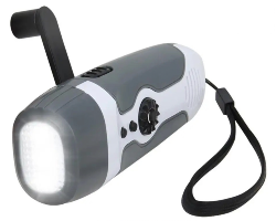
You have to turn the motor pretty fast though to light an LED, but you can make this more efficient by adding some gears. This is how those emergency hand-crank run flashlights work:
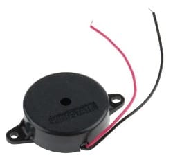
Buzzer (sound)
That annoying eeeeeeeeeee sound you get from cheap alarms and the like comes from a piezo buzzer, which is just an element that vibrates when you put electricity through it, generating waves in the air that our ear interprets as sound.
The sound pitches higher or lower depending how much electricity you run through it. You can also use it backwards, as a vibration/tap sensor, because it generates a tiny bit of electricity with each movement.
Yes, this makes it also possible to harvest energy from vibrations with it, like so:
Microphones and speakers

Microphones and speakers are based around the same principle of a vibrating diaphragm. Yes, these can also be used in reverse!
- If you plug headphones into a mic jack, you can use them as a makeshift microphone.
- If you plug a microphone into an audio jack, technically speaking it could be used to hear sounds. (Don't actually do this unless you start with the audio output VERY low, or if you don't mind ending up with a broken mic because the output was too much for it.) The quality won't be very good, because the mic diaphragm is small and not designed for this. But if you're on a desert island trying to use a broken radio, this could work.
This is because both speakers and microphones either:
- translate electricity into diaphragm vibrations (speakers), or
- translate vibrations into electricity (microphones)
Classroom applications:
(You don't have to be a teacher to have this be relevant)
So now you know:
- You're generally going to need:
- Power (battery)
- Output element (LED)
- Input or control element (switch)
- Some components work both ways:
- Motors (either turn in response to electricity, or can be turned to make electricity)
- Piezos
- Diaphragm components (Speakers and mics)
Lots of things are about translating electricity to and from a physical form (light, sound)
LEDs are not continuous light, but a series of flashing photons too fast for the eye to see. Our eyes can't process light that fast. You know what we can process pretty fast though?
Sound.
So what if we made a thing that lets us HEAR light?
Materials:
- a 3V coin cell battery for power (like the CR2032)
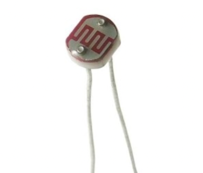
- a photoresistor for input
- a piezo buzzer for output (make sure it's one that works with low voltage)
- A chopstick (So you have a physical structure to stick the components to)
- Some copper tape (To connect the components and wires without solder)
- Some duct tape (to stick everything together)
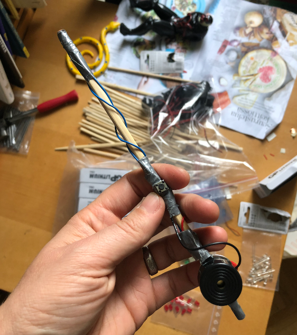
Method:
- Attach wires to each leg of the photoresistor with the copper tape. Fold firmly to make a good connection.
- Put the photoresistor at the tip of the chopstick. Secure the legs and wire connection around the tip with the duct tape.
- Wrap the wire around the length of the chopstick to keep it neat until the bottom.
- Attach one wire to the piezo.
- Attach the other to the battery.
- Touch the free piezo wire to the other side of the battery. (This is a makeshift button. You're opening and closing the corridor by touching and removing the wire from the battery.) You should hear a buzz, unless you're in a totally dark room. If not, check all your connections.
- If it all works, tape the rest of it to the bottom of the chopstick.
Now try holding the wire to the battery so it's "on", and pointing the end of the chopstick towards different lights. You should hear different sounds.
What's happening?
The photoresistor is narrowing and widening the corridor in response to how much light it gets. Since LEDs in household fixtures flash on and off, it's a harsh sound, or what we call a square wave:
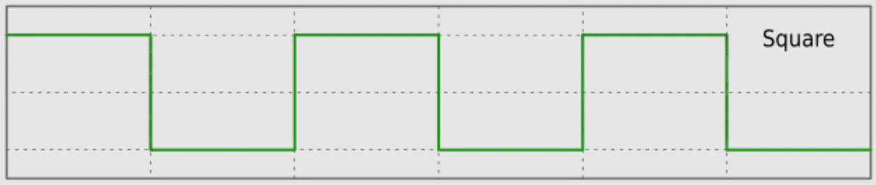
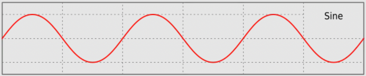
If you wave it towards and away from a continuous source of light (like the sun), you might generate a smooth sounding slow sine wave with the movement of your hand:
Classroom notes for teachers:
- There is nothing particularly exciting about components on their own, just like there isn't anything particularly exciting about a piece of paper. The first question your students are going to be asking themselves is why should I care.
Often students are introduced first to something like the micro:bit or Arduino or the equivalent.
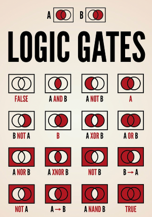
Before these existed, if you wanted to have a light turn on only if a switch was on AND a light sensor was in darkness, you had to use a component called a logic gate. Logic gates come in various forms like AND, OR, NOR and so on.
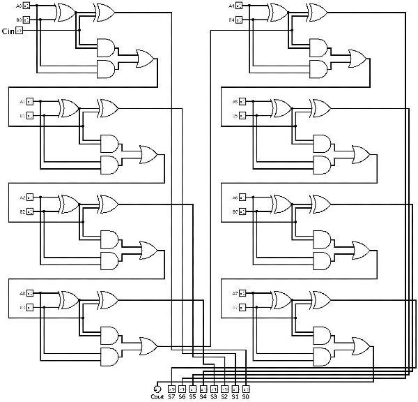
These would then be put together in series and combinations like this:
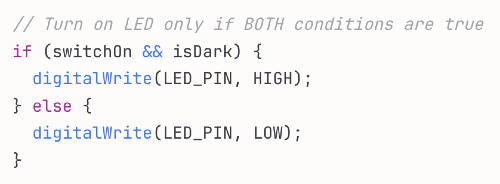
Can't we just tell a circuit what we want? With something more like English? How about Arduino code:
Microcontrollers like the micro:bit or Arduino are simply ways to introduce logic with code instead of physical logic gates. micro:bit is even simpler because it lets you program with code blocks instead of having to type things. It also has buttons and LEDs and sensors already attached to it, so you don't have to wire things to it but can start making it do things without any additional components.
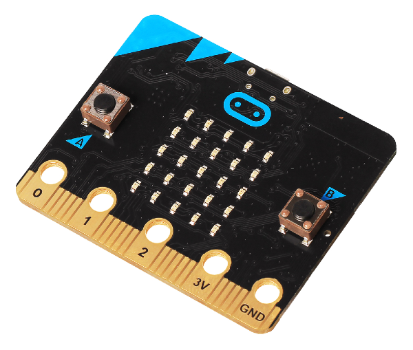
These devices need power, and then you can choose to attach things to their pins (numbered connections to attach a wire to) or use any components that they already have on board. The micro:bit above has a grid of LEDs and two buttons that you can access via the code, for example. So you could write code that says:
"if the right button is pressed, turn the right hand row of LEDS on. If the left button is pressed, turn the left hand row of LEDs on"
Or if you want to use the pins, you could say:
"Pin 0 is my light. Pin 1 is my light sensor. If Pin 1 is sending no signal, then turn on Pin 0." (This would switch a light on when dark)
Exciting, right? WRONG
These are often just handed to teenagers with the expectation that they will be instantly fascinated by the "endless possibilities". Why should they be? You can go through a ton of effort to make one light turn on and off. Who cares?
What the teachers failed to convey was where this was all supposed to lead.
First choose a goal
This is why I recommend starting with the basic circuits first. There's no point in introducing a kid to a thing designed to make complex logic simple, when that kid has no NEED to make something complex yet.
Instead, present goals, first starting with goals you can achieve with basic components, and then goals that could be done either with basic components or a microcontroller, and finally goals that are really going to need a microcontroller.
For example:
- make an alarm to protect your stuff
- make something to prank someone with
- make something you can use to communicate secretly in class (a good moment to introduce infrared sensors and LEDs)
- make a board game with lights and sound effects
Let them brainstorm a solution, make sure it's within their capabilities, and if they get ambitious THEN give them a microcontroller. This changes the focus from "I don't even know why I'm doing this" to "how can I get this done?"
If the project includes a microcontroller, it makes sense to put them in teams where tasks can be divided by coding, designing and making the physical enclosure or structure, and possibly wiring components correctly.
The overall rule of thumb is get out of the way and let them chase their own goals. Answer questions when they hit obstacles, but don't have them follow some formulaic recipe with no idea why they would bother to in the first place. As one of my teachers once said, if you teach teenagers, don't be boring.
Harvesting your own components
Another thing you can introduce to students is that they can use their knowledge to actually fix things, or to take a broken thing apart and harvest components out of it to make a new thing, like they do in sci-fi movies. My father used to regularly call me over to take apart anything that broke in our house to "see what it had eaten". This is a great way to both learn and get comfortable with the innards of the objects around you.
- Bring in old toys(flea markets have lots), ideally ones with lights and sounds and movement. Doesn't matter if they work or not. The cheaper, the better.
- Take them apart and identify components. "There's an LED!" etc.
- Snip components off with pliers and leave their "legs" as long as possible so they're easier to handle.
- Some toys will have components soldered flat to the surface of a circuit board. Nevermind those. However, toys like those blinky swords and "wands" you sometimes get from amusement parks (which have plastic housings that easily crack, while the components inside are fine, making "broken" ones a great source for components) usually have easily removeable:
- LEDs
- Motors
- Battery holders
- Speakers or piezos
- wires
- Also if the toys are broken, you can point out that often electronics break because there's a break in some connection. So if they follow the wires, they might find someplace that isn't making contact (usually the battery compartment)
In the end, what you want your students left with is the confidence that none of this is rocket science, and it will come in useful even if they have no interest in becoming electrical engineers. Having agency over your environment is a powerful thing, and electricity is part of the fabric of our world.
Good luck!
Useful links for further study:
Tutorials, component sources and project ideas:
Bonus: Another metaphor to explain voltage: https://learn.sparkfun.com/tutorials/what-is-a-circuit